Servo motors are the backbone of modern automation, robotics, and precision motion control systems. Understanding the various servo operation modes is essential for engineers, technicians, and hobbyists who want to optimize performance, accuracy, and efficiency in their applications. From simple hobby servos controlled by PWM signals to advanced industrial servodrives with multi-mode feedback loops, each mode offers unique capabilities tailored to specific motion tasks. In this comprehensive guide, you will learn about position control, velocity control, torque control, and synchronized cyclic modes, along with practical insights into choosing the right mode for your project.
What Is a Servo Motor and How Does It Operate?
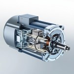
A servo motor is a closed-loop rotary or linear actuator that uses position feedback to precisely control its angular or linear position, velocity, and acceleration. It consists of a motor, a position sensor (usually an encoder or potentiometer), and a control circuit. The control circuit continuously compares the commanded value with the actual feedback value and adjusts the motor output to minimize the error. This feedback mechanism is what gives servos their renowned accuracy, repeatability, and fast response time in comparison to standard DC or stepper motors.
Common Servo Operation Modes Explained
Modern servodrives support multiple operation modes, defined by standards such as CiA 402 (CANopen) and various proprietary protocols. Below are the most widely used servo operation modes in industrial and commercial applications.
1. Position Control Mode (PP – Profile Position)
In Position Control Mode, the servo moves to and holds a specific target position commanded by the controller. It uses an internal trajectory generator to produce smooth motion profiles based on parameters such as target position, profile velocity, acceleration, and deceleration. This mode is widely used in:
- CNC machines and 3D printers
- Robotic arm joint positioning
- Pick-and-place assembly systems
- Camera gimbal stabilization
2. Velocity Control Mode (PV – Profile Velocity)
In Velocity Control Mode, the servo maintains a target rotational speed independent of load variations. The drive continuously regulates the motor speed by adjusting voltage or current based on feedback from the encoder. This mode is ideal for:
- Conveyor belt systems
- Spindle drives
- Pumps and fans
- Continuous-feed manufacturing processes
3. Torque Control Mode (PT – Profile Torque)
In Torque Control Mode, the servo regulates the output torque or current to a commanded value. The drive ensures a constant force regardless of position or speed. This mode is often used in applications where controlled tension is critical, such as:
- Winding and unwinding machines
- Tension control systems
- Force-feedback robotic applications
- Press machines
4. Homing Mode (HM)
Before normal operation, a servo must establish a defined reference position, also known as the mechanical zero point. The Homing Mode automates this process by moving the motor to a homing switch, limit sensor, or index pulse. Methods include:
- Homing on the negative limit switch
- Homing on the positive limit switch
- Homing on the home switch with index pulse
- Homing to the current position (set home directly)
5. Cyclic Synchronous Position (CSP) Mode
In CSP mode, the master controller computes the trajectory in real time and sends periodic target position updates to the servo drive. The drive executes only the position control loop, while velocity and current loops run internally. This provides extremely low latency and is the preferred mode for high-performance robotics and CNC machining.
6. Cyclic Synchronous Velocity (CSV) Mode
In CSV mode, the master controller streams velocity commands at fixed cycle intervals, while the drive handles the current/torque loop. This mode balances controller workload and communication bandwidth, making it suitable for coordinated multi-axis motion in real-time systems like EtherCAT and PROFINET IRT.
7. Cyclic Synchronous Torque (CST) Mode
In CST mode, the master directly controls the torque output, and the drive manages only the current control loop. This is the most responsive mode and is used in advanced applications such as force-controlled robotics, compliance control, and impedance control.
Servo Operation Modes Comparison Table
The following table summarizes the key differences between each major operation mode to help you select the right one for your project:
| Mode |
Controlled Variable |
Typical Use Case |
Controller Workload |
| Profile Position (PP) |
Target Position |
CNC, 3D printing, robotics |
Low |
| Profile Velocity (PV) |
Target Velocity |
Conveyors, pumps |
Low |
| Profile Torque (PT) |
Target Torque |
Winders, tensioners |
Low |
| Cyclic Sync Position (CSP) |
Position (real-time) |
High-speed multi-axis |
High |
| Cyclic Sync Velocity (CSV) |
Velocity (real-time) |
Coordinated motion |
High |
| Cyclic Sync Torque (CST) |
Torque (real-time) |
Force control robots |
Very High |
| Homing (HM) |
Reference Position |
Startup calibration |
Low |
How to Choose the Right Servo Operation Mode
Selecting the correct mode depends on your application requirements, communication bandwidth, and real-time processing capability. Use the following decision criteria:
- Point-to-point motion? Use Profile Position (PP) mode.
- Constant speed required? Use Profile Velocity (PV) mode.
- Force or tension regulation? Use Profile Torque (PT) or CST mode.
- Real-time multi-axis synchronization? Use CSP, CSV, or CST modes.
- Simple hobby project? PWM-based hobby servos in position mode are sufficient.