
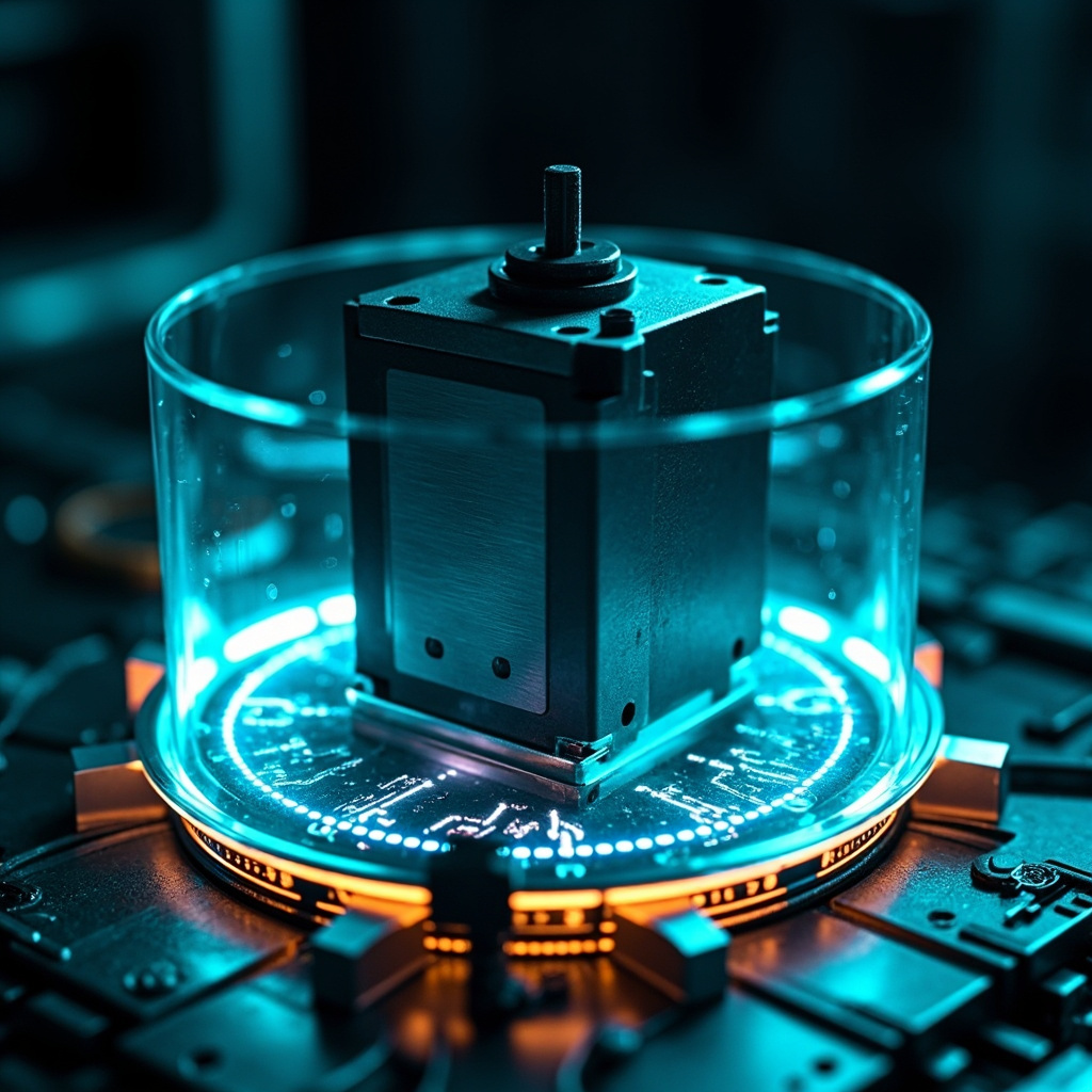
In modern industrial automation, servo systems serve as the backbone of precision motion control across robotics, CNC machinery, packaging lines, and countless other applications. However, even the most robust servo motors are vulnerable to mechanical and electrical stress that can cause permanent damage, costly downtime, and safety hazards. This is where servo overload protection becomes essential—a sophisticated suite of mechanisms designed to monitor, detect, and respond to abnormal operating conditions before catastrophic failure occurs.
This guide explores the principles, components, diagnostic methods, and best practices behind effective servo overload protection. Whether you are a controls engineer, maintenance technician, or system integrator, understanding these concepts will help you maximize equipment reliability, extend service life, and maintain production efficiency.
What Is Servo Overload Protection?
Servo overload protection refers to a combination of hardware and software safeguards built into servo drives and controllers that prevent the motor and drive from operating beyond their rated electrical, thermal, or mechanical limits. When an overload condition is detected, the protection system typically responds by reducing torque output, issuing a warning, or triggering an emergency stop.
Unlike simple fuses or circuit breakers that respond only to overcurrent events, modern servo protection systems continuously evaluate multiple parameters in real time, including current, voltage, temperature, speed, and position feedback. This multi-layered approach ensures that transient spikes and gradual degradation are both addressed.
Why Servo Overload Protection Matters
Servo motors are precision components designed to operate within tightly controlled parameters. Exceeding these limits—even briefly—can cause:
- Insulation breakdown in motor windings due to excessive heat
- Demagnetization of permanent magnets in the rotor
- Bearing wear and premature mechanical failure
- Encoder damage leading to position feedback errors
- Drive IGBT failure from sustained overcurrent conditions
- Production losses from unplanned downtime and emergency repairs
Investing in proper overload protection reduces total cost of ownership, improves workplace safety, and ensures compliance with industry standards such as IEC 61800 and UL 508C.
Common Causes of Servo Overload
Understanding the root causes of overload events is the first step toward preventing them. The most frequent triggers include:
- Mechanical jamming – Foreign debris, misaligned couplings, or seized bearings create sudden resistance.
- Excessive load inertia – The load’s mass or inertia ratio exceeds the drive’s capacity to accelerate or decelerate it.
- Improper tuning – Poorly configured PID gains cause oscillation, overshoot, and current spikes.
- Voltage transients – Power supply fluctuations or regenerative energy from rapid deceleration.
- Thermal stress – High ambient temperatures, restricted airflow, or failed cooling fans.
- Wiring faults – Loose connections, short circuits, or ground faults.
How Servo Overload Protection Works
Servo overload protection operates through several coordinated layers:
1. Current Monitoring
The drive continuously measures phase current using shunt resistors or Hall-effect sensors. When current exceeds a programmed threshold for a defined duration, the drive triggers a current overload fault. Many drives use an I²T (current squared times time) algorithm that mimics the thermal behavior of the motor windings, allowing brief current spikes while protecting against sustained overloads.
2. Thermal Protection
Built-in thermal models calculate motor and drive temperatures based on current draw, ambient conditions, and cooling effectiveness. Additionally, many servo motors embed PTC thermistors or KTY temperature sensors that provide direct feedback to the drive. If temperatures exceed safe limits, the drive reduces output or shuts down completely.
3. Regenerative Energy Management
When a servo decelerates a load, kinetic energy is converted back into electrical energy. If not dissipated, this regenerative energy can raise the DC bus voltage to dangerous levels. Protection circuits engage braking resistors or use regenerative drives to safely absorb this energy.
4. Position and Following Error Protection
The drive compares the commanded position with the actual position reported by the encoder. If the difference (following error) exceeds a configurable limit, the drive assumes a mechanical issue and triggers a fault to prevent runaway motion.
Comparison of Protection Methods
| Protection Type | Response Time | Typical Use Case | Limitations |
|---|---|---|---|
| Electronic Thermal Overload | Seconds to minutes | General motor protection | Reacts to gradual heating |
| Instantaneous Overcurrent (OC) | Microseconds | Short circuits, ground faults | No tolerance for legitimate inrush |
| Following Error Detection | Milliseconds | Mechanical jams, encoder issues | Requires precise tuning |
| Regenerative Braking | Continuous | High-inertia deceleration | Requires external resistor sizing |
| PTC/KTY Temperature Sensor | Seconds | Direct winding temperature | Adds wiring complexity |
⚠️ Pro Tip: Always size your braking resistor to handle the worst-case deceleration of the heaviest load. An undersized resistor can overheat and fail, leaving your drive exposed to overvoltage faults. Use the formula: Presistor = (J × ω²) / 2 × (1/t), where J is inertia, ω is angular velocity, and t is deceleration time.
Best Practices for Implementing Overload Protection
- Right-size the servo – Select a motor and drive with at least 25–30% headroom above peak calculated load.
- Validate inertia ratios – Keep load-to-motor inertia ratios within manufacturer-recommended limits (typically 10:1 or less for standard servos).
- Tune conservatively – Start with low PID gains and increase gradually to avoid oscillation and current overshoot.
- Monitor trends – Use drive diagnostic tools to log overload events, temperatures, and current over time.
- Implement safe stops – Configure controlled stop sequences (Category 1 or 2 stops per IEC 60204) instead of coast-down stops.
- Schedule preventive maintenance – Inspect cooling fans, clean heat sinks, and check connections quarterly.
- Document fault codes – Maintain a library of drive alarm codes and their root causes for faster troubleshooting.
Troubleshooting Common Overload Faults
When an overload fault occurs, follow this systematic approach:
- Check the fault history in the drive to identify which protection triggered and the values at the time of the event.
- Inspect mechanical components for binding, misalignment, or contamination.
- Measure actual load with a torque wrench or dynamometer to confirm it is within ratings.
- Verify electrical supply – Check for voltage imbalance, harmonic distortion, or sag.
- Review motion profiles – Reduce acceleration/deceleration rates if current peaks are excessive.
- Recalibrate feedback – Re-home encoders and verify resolver or absolute encoder alignment.
Browse topics
Categories
Latest insights
Recent posts
- Mastering Multi-Task Program Management: Strategies for Success in 20262026年8月31日
- Coordinate System Switching: A Complete Guide to Seamless Map Projections Transformation2026年8月29日
- Understanding Program Loop Execution: A Complete Guide to Efficient Iteration in Code2026年8月27日
- How to Calculate MTTR (Mean Time to Repair): Formula, Examples & Best Practices2026年8月25日
- MTBF Calculation: A Complete Guide to Mean Time Between Failures2026年8月23日
Browse topics
Categories
Latest insights
Recent posts
- Mastering Multi-Task Program Management: Strategies for Success in 20262026年8月31日
- Coordinate System Switching: A Complete Guide to Seamless Map Projections Transformation2026年8月29日
- Understanding Program Loop Execution: A Complete Guide to Efficient Iteration in Code2026年8月27日
- How to Calculate MTTR (Mean Time to Repair): Formula, Examples & Best Practices2026年8月25日
- MTBF Calculation: A Complete Guide to Mean Time Between Failures2026年8月23日
Discover more from Xiamen Lisen Trading Co., Ltd
Subscribe now to keep reading and get access to the full archive.