
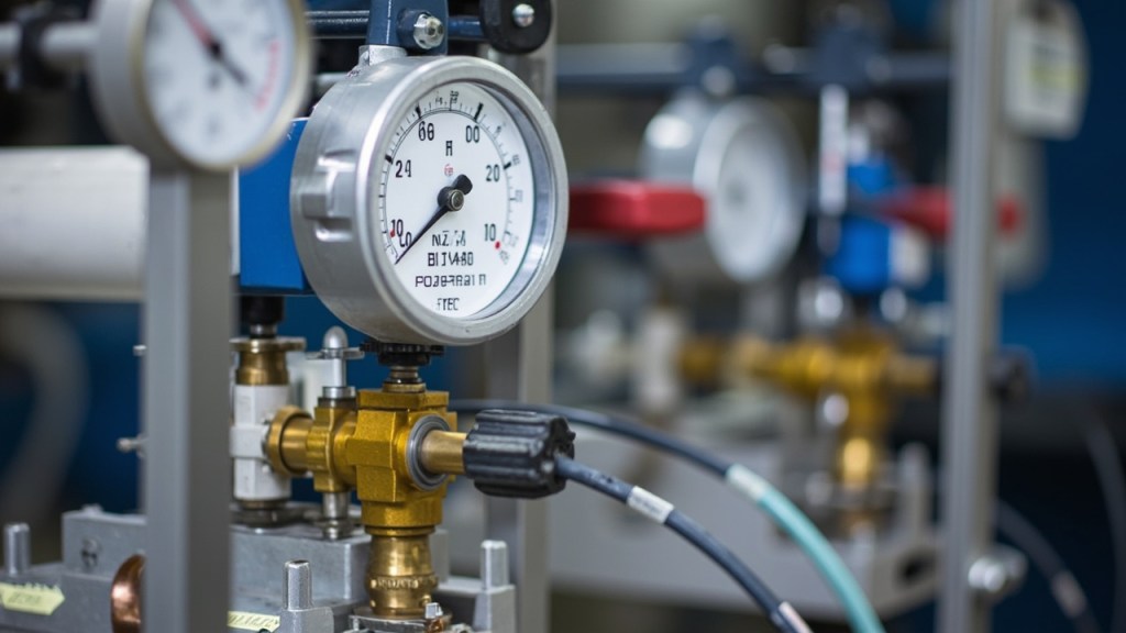

Positive Displacement Flow Meter Selection for Hydraulic Oil: KRACHT VC 1 F1 PS Accuracy, Aquametro VZF 40 Range, and VZO 20 Turndown
Selecting a positive displacement flow meter for hydraulic oil requires balancing rated pressure, minimum operating flow, connection size, fluid characteristics, accuracy, and signal output. A meter can offer excellent nominal accuracy yet still produce an unreliable measurement if it is oversized for the line, operated outside its pressure envelope, or installed where air can enter the measuring chamber. The KRACHT VC 1 F1 PS, Aquametro VZF 40 FL 180/25, AquaMetro VZO 20 RC 130/16, and smaller catalogue options illustrate why range and error basis must be evaluated together. This guide examines how these instruments work, compares their turndown characteristics, explains the difference between percentage-of-reading and percentage-of-full-scale accuracy, and connects flow velocity to port sizing. It also covers pressure ratings, electrical outputs, installation practices, and the practical checks that help preserve measurement integrity.
What a Positive Displacement Meter Actually Counts
A positive displacement meter measures a fixed volume for each cycle of an internal rotating element. In a gear meter, that element repeatedly exposes and fills a defined measuring chamber. Shaft revolutions are therefore proportional to the volume that has passed, and the electronics can determine flow from the rotation rate. This is why the principle is appropriate for oil and fuel: the liquid is divided into repeatable internal volumes rather than inferred from velocity through a partially filled pipe.
The arrangement also explains its limitations. The liquid must follow a defined flow path through the measuring chambers, so gas and large debris must be excluded. Unlike a turbine meter, a gear meter does not depend on a minimum velocity to generate pulses. However, clearance leakage between the rotating element and the body becomes more significant as viscosity falls. A meter calibrated with one fluid therefore cannot be transferred automatically to another oil or fuel without checking the manufacturer’s correction data.
Several catalogue items use related positive displacement technology. The KRACHT VC 1 F1 PS gear flow meter is listed for a range of 0.5 to 60 L/min with accuracy of plus or minus 0.5 percent of reading. The Aquametro VZF 40 flow meter is listed for oil and viscous fluids over 1 to 100 L/min with the same accuracy basis. The AquaMetro VZO 20 fuel flow meter is listed from 2 to 20 L/min for fuel service.
Turndown Is the Ratio That Decides the Size
Turndown is calculated here as the top of the stated range divided by the bottom of that range. For the KRACHT VC 1 F1 PS, 60 L/min divided by 0.5 L/min gives a turndown of 120 to 1. For the Aquametro VZF 40, 100 L/min divided by 1 L/min gives 100 to 1. The KRACHT VC0.1F1PS/71 flow sensor has a listed range of 0.1 to 10 L/min, so 10 divided by 0.1 gives 100 to 1. The AquaMetro VZO 20 has a listed range of 2 to 20 L/min, producing a turndown of 10 to 1.
That last ratio is the critical distinction. A 10 to 1 meter must be sized against the actual minimum flow. If the system spends substantial time below 2 L/min, the meter is operating in territory its stated range does not cover. The reading may become unstable or untrustworthy rather than simply following the original calibration trend.
The wide-ratio instruments are better suited to test benches that idle and then run hard because their stated range extends over a broad operating span. Nevertheless, turndown does not relieve the installer of checking line velocity, pressure, and fluid compatibility. It also does not guarantee the same accuracy basis across every point in the range. A useful selection method is to establish the minimum and maximum operating flows first, select a meter whose range contains both with practical margin, and then verify what the manufacturer means by accuracy at the low-flow end.
Percent of Reading and Percent of Full Scale Are Different Promises
The VC 1 F1 PS and VZF 40 are listed at plus or minus 0.5 percent of reading. At 5 L/min, the resulting uncertainty band is 0.025 L/min. At 60 L/min on the KRACHT, it is 0.3 L/min. This basis holds the relative error approximately constant across the range, so the absolute error grows with the measured flow.
The VZO 20 is listed at plus or minus 1 percent of full scale on a 20 L/min upper range. The uncertainty band is therefore 0.2 L/min wherever it is measuring. At 5 L/min, that band equals 4 percent of the displayed value; at 20 L/min, it equals 1 percent. This is a different performance promise from percentage of reading.
The VC0.1F1PS/71 listing states plus or minus 1 percent without identifying the basis. That omission matters. The manufacturer data sheet must be consulted to establish whether the claim refers to reading or full scale. Other listed details for this sensor include a 4–20 mA output, stainless steel construction, operating pressure up to 40 bar, 24 V DC supply, and a listed weight of 0.3 kg. It is also listed for water, oil, and chemicals.
Before purchase, convert the accuracy claim into an acceptable error at the lowest important operating flow. If the measurement controls a dispensing decision, an absolute volume tolerance may be more useful than a percentage. If it monitors process stability, relative performance near normal flow may matter more. The correct basis must be confirmed rather than inferred from the percentage alone.
Line Velocity, Port Size and What DN Does Not Mean
Mean line velocity is calculated as volumetric flow divided by the internal bore area. The units must remain consistent: cubic millimetres per second divided by square millimetres produces millimetres per second, which can then be converted to metres per second.
At the top of the VZF 40 range, 100 L/min is approximately 1.67 litres per second, or 1,670,000 cubic millimetres per second. A 40 mm bore has an area of roughly 1,257 square millimetres. The indicative order-of-magnitude velocity is therefore about 1.3 m/s, which is ordinary for an oil line.
Now consider the KRACHT meter with a range ending at 60 L/min but a nominal size and connection listed as DN 6, given as 1/4 inch. Applying the same calculation to a 6.35 mm bore, with an area of about 31.7 square millimetres, gives roughly 30 m/s. No ordinary hydraulic line is designed for that result. The chamber of a gear meter and the pipe carrying its output are different questions: the meter must accommodate the flow internally, while the connected line must have enough bore to keep velocity reasonable.
Accordingly, the top of a stated meter range is usable only when the piping is sized for a sane velocity. A DN number on a listing is a connection or nominal designation, not permission to force a given flow through that bore. Confirm the internal bore, the installed pipe dimensions, and the manufacturer’s permitted flow range before ordering.
Pressure Class Comes Before Accuracy
Pressure capability establishes whether an instrument can survive the circuit; accuracy determines how well it measures after survival is assured. The VC 1 F1 PS is listed at a maximum pressure of 315 bar. Its listed specifications also include a G 1/4 BSPP threaded process connection, 24 V DC, CE, ATEX and ISO 9001, a weight of 1.2 kg, and a calibration certificate listed in the box.
Other catalogue figures show clearly different pressure envelopes. The KF40 RF 2/197-D15 oil pump is listed for 40 litres per minute, pressure up to 210 bar, a temperature range of -20 C to +80 C, flange mounting, and cast iron and steel construction. The ASR20-1DOS-PB DN20 electrically actuated hydraulic directional control valve is listed for operating pressure up to 315 bar and 24 V DC. In a broader review of actuator and circuit layout, our Rexroth directional control valve selection guide can help identify the function and pressure context of directional valves.
By contrast, the VZF 40 is listed at a maximum pressure of 25 bar, while the VZO 20 is listed at 16 bar. The VC0.1F1PS/71 is listed up to 40 bar. A fuel or transfer meter rated at 25 bar cannot simply be installed in a working hydraulic line that operates far above that level. A meter with a 25 bar maximum also provides no allowance for pressure spikes generated when a directional valve closes.
Selection must therefore begin with the pressure and temperature envelope of the complete wetted path, including seals and transmitter electronics, before considering accuracy. Spike protection belongs to the hydraulic circuit design, not to the meter’s nameplate. Where flow and pressure must be considered together in rotating equipment, the principles behind Danfoss orbital motor selection provide a useful adjacent reference.
Pulse, Analog or Contact: Getting the Number Out
A pulse output represents volume indirectly. The total volume is calculated as pulse count divided by the meter factor in pulses per litre. Where our listing includes a calibration certificate in the box, the individual meter factor can be tied to that document rather than estimated from a generic nominal value. This applies to the listed VC 1 F1 PS and VZF 40 configurations. Both meters are also listed with 4–20 mA plus pulse output where applicable, while the VZF 40 carries 24 V DC and a listed weight of 2.5 kg.
A 4–20 mA output is a rate signal that the control system scales. The VZF 40 and VZO 20 are listed with analog and pulse availability, allowing one instrument to support both totalised volume and rate-based alarms or control functions. A loop-powered meter still needs its supply included in the panel design; the relevant listings specify 24 V DC.
The HONSBERG VD 40 RI 410829 is different. It is a mechanical flow switch with a DN 40 threaded connection and a flow-dependent microswitch contact. Our listing gives the maximum switching voltage as 250 V AC or 30 V DC, covers water and compatible low-viscosity liquids, and specifies inline installation in a horizontal pipe with an approximate weight of 0.8 kg. It indicates that a threshold has been reached; it does not measure quantity. The contact should therefore operate a control circuit through a relay rather than switch a load directly.
Installation determines whether any accuracy survives. The following duties deserve attention before commissioning:
- Provide full-bore isolation valves and a bypass for filter cleaning.
- Follow the flow-direction arrow and install the straight runs required by the manufacturer drawing.
- Select an upstream strainer according to the meter’s clearances rather than merely the pipe size.
- Mount the meter where the line remains filled, avoiding arrangements that drain back.
- Compare the totaliser against a known volume during commissioning.
A meter in a vertical line that drains back can treat a slug of air as liquid product. Priming, valve sequencing, and a known-volume check are therefore part of measurement quality, not optional finishing work.
| Meter or device | What our listing states (range, accuracy, pressure) | Where it fits | What you must still confirm |
|---|---|---|---|
| KRACHT VC 1 F1 PS | 0.5–60 L/min; plus or minus 0.5 percent of reading; maximum pressure 315 bar | High-pressure hydraulic oil measurement where a wide turndown is required | Bore-compatible piping, actual viscosity correction, pulse factor, and full installation clearances |
| Aquametro VZF 40 FL 180/25 | 1–100 L/min; plus or minus 0.5 percent of reading; maximum pressure 25 bar | Oil and viscous-fluid transfer at moderate line pressure | Pressure spikes, oil compatibility, minimum stable flow, and the exact output configuration |
| AquaMetro VZO 20 RC 130/16 | 2–20 L/min; plus or minus 1 percent of full scale; maximum pressure 16 bar | Fuel-service metering with analog or pulse output | Whether minimum system flow stays above 2 L/min and whether circuit pressure fits the rating |
| HONSBERG VD 40 RI 410829 | Flow-dependent microswitch; DN 40 threaded connection; no flow-measurement accuracy stated | Threshold indication in water or compatible low-viscosity liquids | Actual switch points, horizontal installation, liquid compatibility, and relay interface requirements |
Frequently Asked Questions
Which of these meters has the widest listed turndown?
Using top divided by bottom, the VC 1 F1 PS has the widest listed range at 120 to 1. The VZF 40 and VC0.1F1PS/71 each provide a listed 100 to 1 range, while the VZO 20 is listed at 10 to 1.
Does plus or minus 0.5 percent mean the same thing at every flow?
No. For a meter quoted by percentage of reading, the relative error remains approximately constant. A percentage-of-full-scale meter maintains a fixed absolute error, so its error becomes larger relative to the displayed value as flow falls.
Can the VZF 40 be installed in a high-pressure hydraulic line?
Only if the complete system remains within its listed pressure envelope. Our listing gives the VZF 40 a maximum pressure of 25 bar, so high-pressure operation, including valve-closing spikes, requires a different meter or circuit design.
Is a 4–20 mA output enough for batch totalisation?
A 4–20 mA signal provides instantaneous rate, but totalisation also requires the control system to integrate and preserve that rate. A pulse output with a documented meter factor supports an independent volume total, so analog and pulse together provide useful flexibility.
Which installation checks are most important?
Keep the meter full, respect flow direction and required straight runs, provide isolation and filtration arrangements, and verify the indicated total against a known volume at commissioning. These checks expose air ingress, incorrect valve sequencing, and unsuitable flow conditions.
Conclusion
The best positive displacement meter is not simply the one with the highest accuracy percentage. It is the instrument whose pressure rating, flow range, connection, fluid behavior, error basis, and output match the actual circuit. The VC 1 F1 PS offers a wide listed range at a high pressure rating, the VZF 40 suits moderate-pressure oil service, the VZO 20 provides a narrower fuel-metering range, and the HONSBERG device serves as a threshold switch rather than a measuring instrument.
Our team can cross-reference the exact part number against your hydraulic system, confirm the required configuration, and check the current lead time before you order. Contact us with the model identifier, operating fluid, pressure, minimum and maximum flow, connection details, and preferred output so we can narrow the selection efficiently.