
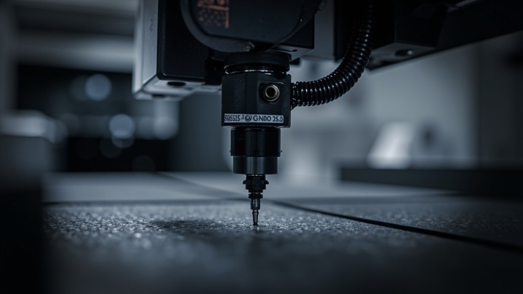
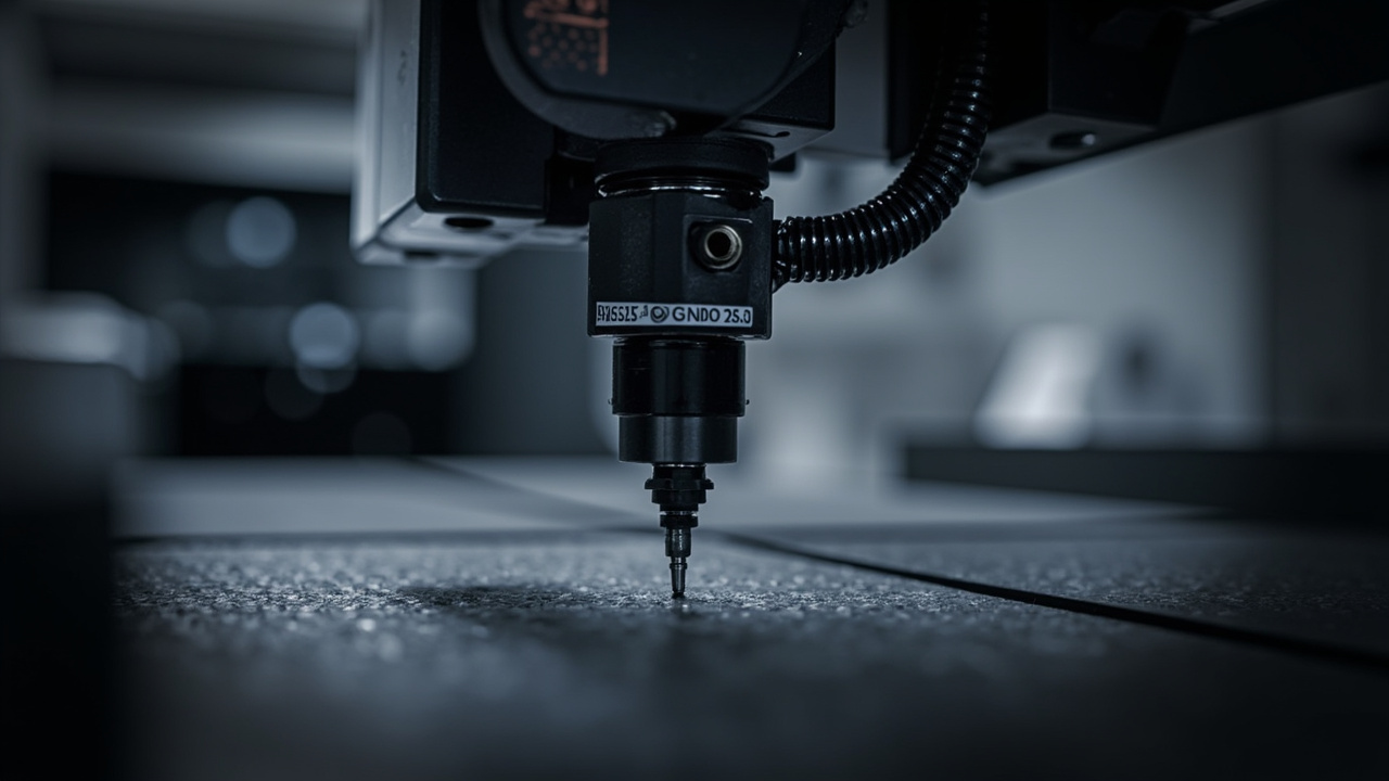
CNC In-Process Gauging and Measurement Chain: Renishaw A-1371-0271 Force Module, A-5000-7522 Stylus, T1030-30A Readhead and TI2000A40A Interpolator
In-process measurement is often described as a probe, but the probe is only the visible end of a larger measurement chain. A spindle-mounted touch probe detects a surface, converts movement into an electrical signal, and reports a position to the CNC control. That report is meaningful only when the stylus geometry, trigger force, axis feedback, digital counting, and control compensation are working together. Each stage contributes uncertainty, so a high-quality probe cannot compensate for a drifting scale, contaminated optical path, or poorly qualified stylus. This article examines the listed Renishaw components as parts of that chain and explains why exact identification, installation discipline, and verification remain essential.
In-Process Gauging Is a Chain, Not a Probe
The first stage is physical contact between the stylus and the workpiece. The next is the trigger element, which detects a force-induced movement and generates a signal. Axis feedback then establishes where the machine axis was when that signal occurred. Electronic interpolation converts the feedback waveform into counts, while the CNC control applies calibration and compensation values before calculating a measured feature. The result is a combined estimate rather than a direct observation.
That architecture makes error budgeting unavoidable. Stylus bending, trigger repeatability, scale resolution, optical alignment, electrical noise, thermal movement, and control calibration can each introduce uncertainty. A good probe operating on an unstable feedback chain still produces poor measurements. Conversely, excellent position feedback cannot correct a bent or incorrectly mounted stylus.
The Renishaw A-1371-0271 force measurement module should therefore be evaluated together with the mechanical and electronic stages. The listed A-5000-7522 stylus establishes the contact geometry, while the listed T1030-30A readhead and TI2000A40A interpolator belong to the position-sensing side. A useful maintenance strategy identifies the complete chain before replacing an individual component.
Trigger Force and the A-1371-0271 Measurement Module
Contact trigger behavior depends on both force and mechanical stiffness. For a simplified compliant arm, deflection is:
delta = F / k
Here, delta is displacement in millimetres, F is force in newtons, and k is stiffness in newtons per millimetre. A softer arm or longer extension lowers effective stiffness, so the same applied force produces greater movement before triggering. That additional pre-travel can vary with approach direction and may introduce wander if the arm is not stable. No stiffness value is stated for the listed probe, so its effective compliance must be established through the applicable manufacturer documentation and qualification procedure.
Our listing describes the Renishaw A-1371-0271-01 as a precision force measurement module with a 5 V DC supply, a force range of 0.5 N to 5 N, and an analog 0 to 5 V output. Quoting the force range is more useful than treating the stylus as rigid because force, displacement, and triggering are coupled. The module measures force electrically; it does not remove geometric errors in the contact point.
The analog output also places noise and electrical loading within the measurement path. Cable condition, grounding, shielding, and control-side configuration can affect the usable signal. Operators should not interpret the stated range as proof of accuracy across an entire machine installation. Force calibration, probe orientation, trigger settings, and repeatability tests determine how the listed specifications translate into process performance.
Stylus Geometry: Why the A-5000-7522 Is Not Interchangeable
The listed Renishaw A-5000-7522 is a touch probe stylus assembly with a synthetic ruby ball, an M2 thread, and approximate dimensions of 100 x 8 x 8 mm. Each feature affects the measurement point. Length changes bending behavior and reach. Ball diameter changes the contact geometry and the way a surface is located. Thread fit determines whether the stylus seats in the correct position and orientation.
A partially engaged M2 thread can create a repeatable offset, which is particularly dangerous because the probe may continue to trigger normally. Small adapters therefore require careful installation torque, clean threads, and positive seating. The connector and stylus should be checked for damage rather than relying on force alone.
Material selection is another distinction. A synthetic ruby ball provides a defined contact point and predictable wear behavior; it does not make every geometrically different stylus interchangeable. An operator extending the stylus to reach a deeper feature changes length, stiffness, reach, and potentially the effective trigger point. That modified configuration must be requalified in the control.
The Renishaw A-5000-7522 touch probe stylus should therefore be treated as a calibrated part of the measuring system. Verify the specified ball, thread, and assembly dimensions before fitting. If an extension or adapter is introduced, repeat the tip-diameter and approach-direction qualification rather than assuming the original calibration still applies.
Position Feedback: T1030-30A Readhead and TI2000A40A Interpolation
A glass scale contains a periodic grating. A readhead observes that grating and produces two sinusoidal channels approximately a quarter of a grating period out of phase. The listed Renishaw T1030-30A optical encoder readhead provides a TTL / Sin-Cos interface, a stated resolution of 1 um, an IP67 rating, and a 5 V DC supply. It converts physical motion into phase-related signals, but it does not independently establish the machine’s positional accuracy.
The associated Renishaw TI2000A40A signal interpolator has a stated interpolation factor of 40x, accepts a 1 Vpp sinusoidal input, and provides a digital quadrature TTL output. Symbolically, if the grating period is p in micrometres, the counted resolution is:
counted resolution = p / 40
Both p and counted resolution must be expressed in micrometres. Interpolation increases available count resolution by subdividing the grating period; it cannot remove errors already present in the optical signal. Grating error, channel amplitude imbalance, phase error, contamination, and incorrect setup remain present.
The Renishaw T1030-30A encoder readhead must be mounted with the specified gap and alignment, while the scale must remain clean and correctly supported. A readhead fixed to the moving axis member and a scale fixed to the stationary member establish the intended relative motion; incorrect assignments can create offsets or sensitivity to movement. Reference-mark or index information may also be lost after battery or amplifier changes, requiring the machine procedure to be followed before production measurements are accepted.
Finally, the listed readhead resolution is not a machine accuracy claim. Resolution describes the smallest represented interval, while accuracy includes the complete mechanical and metrological chain. Those quantities should not be substituted for one another.
Cables, Contamination, and the Real Accuracy Budget
The listed 1 Vpp sinusoidal input is a small signal level, so cable routing and termination matter. Long unshielded runs, mixed power routing, and a shield terminated at both ends are common practical causes of jitter. The M12 sensor cable assembly selection resource provides a practical framework for assessing assembly details, while the linear versus rotary encoder selection article supports broader feedback architecture decisions.
An IP67-rated readhead does not make the installed measurement chain immune to coolant mist. A blocked air purge, dirty scale, condensation, or debris at the optical gap can reduce signal quality even when the enclosure rating is appropriate. Inspection should include the scale surface, mounting gap, cable path, connectors, purge arrangement, and evidence of coolant entry.
Thermal expansion must also be included. For a homogeneous material:
change in length = alpha x L x change in temperature
Here, alpha is the expansion coefficient per kelvin, L is the original length in millimetres, and change in temperature is in kelvins. The expansion coefficient depends on material and temperature range, so it should not be assigned to a particular listed component without supporting data. A small temperature change across a long steel structure can still be comparable with a tight dimensional tolerance. Part temperature, machine soak, coolant temperature, and the time allowed for stabilization therefore belong in the accuracy budget.
Verification Routines and Module Changing
Verification should separate repeatability, bias, and linearity. Repeatability asks whether repeated measurements remain close together. Bias asks whether the result is consistently displaced from the reference. Linearity asks whether the error changes with measured size or position. A single set of readings cannot establish all three.
Stylus qualification should confirm the tip diameter and the approach-direction offset in the control. Axis and probe checks can then use ball-bar or step-gauge style methods to examine the combined behavior. The listed Mitutoyo 542-186 linear scale micrometer, with a listed range of 0 to 25 mm and resolution of 0.1 um, is a bench reference for suitable checks; it is not by itself a machine verification. The listed Mitutoyo 12AAM106 surface roughness stylus, with a 5 um diamond tip radius on a sapphire shaft for Surftest-class instruments, belongs to a different measurement class. Its much smaller measuring force and scanning motion are intended to extract a profile amplitude parameter from the instrument’s evaluation, not to provide a dimensional trigger point.
A practical verification sequence is:
- Clean and inspect the stylus, probe interface, scale, readhead mounting, cables, and purge.
- Qualify stylus diameter and approach-direction offsets in the control.
- Check probe repeatability without changing the setup.
- Check axis and probe behavior using suitable reference artifacts.
- Record repeatability, bias, and linearity separately.
- Repeat qualification after any module, stylus, readhead, or electronic change.
The listed Renishaw SCR200 probe module changer rack provides six module positions and compatibility with PH10, PH20, and PH25 probe modules. Its value is repeatable engagement of the mechanical interface across multiple fits. Coupling cleanliness, interface wear, and post-swap requalification remain necessary. Confirm the exact module family in the listing before ordering.
| Element in the chain | What it contributes | Listed figure to check | The way it usually goes wrong |
|---|---|---|---|
| A-1371-0271 force module | Converts contact force into an analog measurement signal | 5 V DC; 0.5 N to 5 N; 0 to 5 V output | Noise, poor seating, or treating the range as total system accuracy |
| A-5000-7522 stylus | Establishes contact point, reach, and mechanical compliance | Synthetic ruby ball; M2 thread; roughly 100 x 8 x 8 mm | Wrong extension, partial thread engagement, or omitted requalification |
| T1030-30A with TI2000A40A | Converts axis motion into interpolated digital counts | Readhead: 1 um resolution, 5 V DC; interpolator: 40x, 1 Vpp input | Dirt, misalignment, electrical noise, or confusing resolution with accuracy |
| SCR200 module changer | Repeats the probe-module mechanical interface | Six positions; PH10, PH20, and PH25 compatibility | Dirty coupling, worn interface, or failure to requalify after swapping |
Frequently Asked Questions
Is a precision force module enough to ensure accurate CNC gauging?
No. It measures force within the stated operating range, but the final result also depends on stylus geometry, trigger behavior, axis feedback, counting electronics, calibration, and the control’s compensation model.
Can a different stylus with the same thread be fitted without changes?
Not automatically. Even with an M2 connection, a different length or ball changes reach, compliance, and contact geometry. The tip and approach-direction offsets must be requalified.
Does interpolation remove all encoder and scale errors?
No. A 40x interpolation factor increases count resolution but does not eliminate grating error, phase error, amplitude imbalance, contamination, or mechanical positioning error.
Is a 0.1 um resolution micrometer sufficient for machine verification?
It can provide a suitable bench reference, but resolution alone does not verify a complete CNC measurement chain. Repeatability, bias, linearity, installation, and control compensation must also be assessed.
Why must a probe module be requalified after changing?
The changer repeats the mechanical coupling, but it does not prove that the new module’s trigger point, orientation, or calibration matches the previous setup. Requalification confirms the actual installed configuration.
In-process gauging is reliable only when the stylus, trigger element, axis feedback, interpolation, control model, and mechanical environment are treated as one measurement system. Exact identification preserves that system’s configuration, while qualification and targeted verification reveal where uncertainty enters the chain.
Our team can cross-reference the exact part number and lead time against your requested configuration. Contact us with the complete measurement-chain requirement so we can check compatibility before you order.