
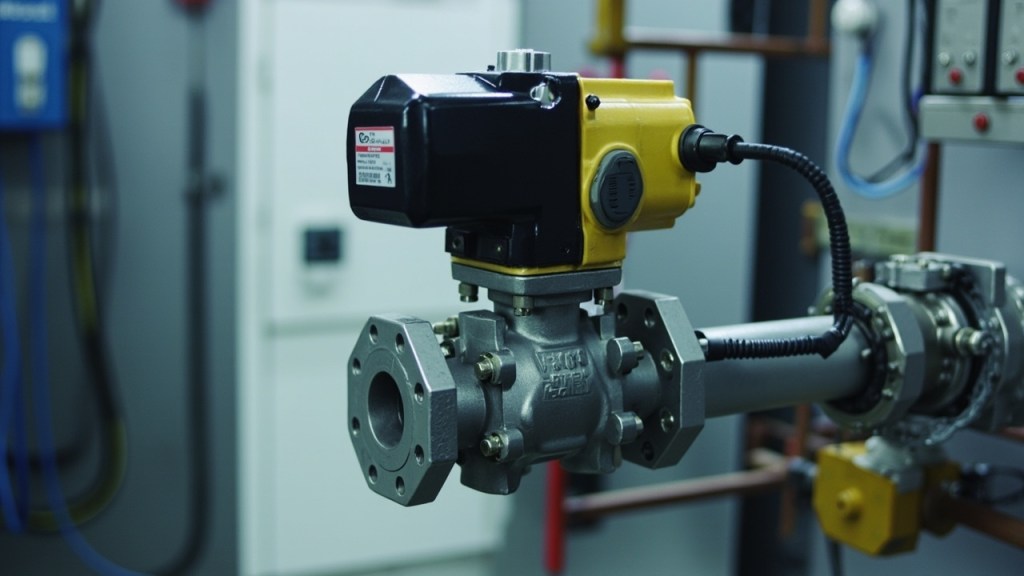
Motorized Valve and Damper Actuator Control: Honeywell Modutrol IV M9484E1017 Wiring, Floating vs Modulating Signal, Spring-Return Fail Position, and Danfoss ETS250 Driver Setup
Selecting a valve or damper actuator involves more than matching a catalogue number to an application. The control signal, electrical terminals, travel limits, mechanical load, fail position, and feedback method must all agree with the controller and final element. A floating actuator may travel until its internal limit switches stop it, while a modulating actuator follows a proportional signal and may require position feedback. Spring-return devices add another layer: their normal state and loss-of-signal behavior must match the safety strategy. The Modutrol IV actuator is one example of a motorized valve actuator whose exact wiring and limits must be confirmed from the manufacturer documentation. This guide explains the engineering relationships behind selection, commissioning, and troubleshooting without assuming specifications that are not stated in the product documentation.
Floating, On-Off, and Modulating: Three Ways to Drive a Final Control Element
On-off control commands one of two positions. A two-wire on-off actuator is energized to move and de-energized to remain in its present or spring-defined state, although the precise terminal arrangement and internal switching must be verified. This method is suitable when the process needs full-open or full-closed operation but not intermediate positioning.
A floating actuator uses separate open, close, and common connections. Energizing the open connection drives the actuator toward one limit; energizing the close connection drives it toward the other. Once the built-in limit switches detect the endpoint, the motor stops. Because travel ends at the actuator’s own limits, external valve-position feedback is not required merely to confirm that the commanded movement has completed. The controller must still know whether it issued an open or close command.
A modulating actuator instead follows a proportional electrical signal, such as 0-10 V DC, 2-10 V DC, or a 4-20 mA signal through a suitable positioner. The controller must match the actuator input type exactly. A floating actuator cannot interpret a proportional signal, and a modulating actuator cannot be wired as though it were a simple open/close device. For modulating systems, position feedback is commonly returned to the controller so it can compare actual travel with the requested position and correct any deviation. Signal compatibility should therefore be checked at the terminals, not inferred from the product family name.
Terminal Logic of a Honeywell Modutrol IV Type Motorized Valve Actuator
The Honeywell M9484E1017 Modutrol IV Motorized Valve Actuator should be treated as an exact-part identification, not a complete wiring specification. Terminal designations, supply requirements, control inputs, limit-switch connections, and motor direction must be confirmed in the applicable Honeywell documentation before field connection. A successful installation depends on identifying which terminals carry the motor windings, internal switches, or external control signals.
For a floating installation, the controller typically provides open, close, and common connections. The internal limit switches interrupt motor power at the selected endpoints, so the actuator does not need to remain powered while holding position. For modulating control, the actuator must receive a signal representing requested travel. A 0-10 V input uses the full signal range across its stated travel, while a 2-10 V input reserves the lower end as a distinct operating condition. A 4-20 mA system introduces a different wiring and polarity check; the 4-20 mA current loop wiring reference is useful when confirming loop continuity and voltage budget.
Motor direction must be verified in a safe, uncoupled condition. Energizing the wrong command can move the linkage toward a valve seat before the intended travel range is established. Auxiliary limit or feedback contacts, if fitted, are not automatically interchangeable with the motor-control terminals. Do not assume that a feedback terminal can carry motor current or control voltage. Wire according to the manufacturer diagram, check terminal labels physically, and record any field changes so a replacement actuator is installed with the same interface.
Damper Actuators and Spring-Return Fail Position
The HVAC Damper Actuator Honeywell M847D-ZONE 24V Control represents a damper-actuation family in which signal type, travel, spring behavior, and mounting orientation determine the final result. A damper actuator may drive directly or through a linkage, and the relationship between actuator movement and blade position must be confirmed rather than inferred from the closed position alone.
A spring-return actuator stores mechanical energy during travel. If the actuator is spring-return, loss of power or control can move the damper toward a predefined position. Fail-closed positions the blade to restrict the airflow path. Fail-open positions it to preserve a flow path. Fail-last-position behavior is also possible in suitable designs, but it requires the manufacturer to support that operating method; it should not be assumed from the presence of a spring alone.
The required failure direction follows the hazard. Combustion-air applications may require a specific closure strategy so fuel cannot continue to flow without adequate air. Freeze-protection arrangements may favor reopening when a valve or damper loses power. Smoke-control systems may require closure or another engineered position. These choices depend on the installation, not on a universal rule.
Orientation can reverse the physical result of the spring action. The M847D damper actuator must be installed so its fail direction matches the intended damper movement. Before coupling the blade, observe the actuator shaft during loss of power or simulated loss of signal. Also verify that the linkage does not bind and that the spring can complete its intended travel without leaving the damper partly open.
Torque, Stroke Time, and Authority: Sizing the Actuator to the Valve or Damper
An actuator must overcome the maximum resistance of the connected valve or damper throughout travel. For a valve, the relevant mechanical load can be influenced by plug diameter, fluid pressure, seat geometry, and flow characteristics. Valve Cv is commonly used when comparing flow capacity, but Cv is not itself a torque specification. The solenoid valve Cv calculation provides useful background on flow-capacity relationships, although an actuator must still be selected against the actual valve’s documented operating forces.
For a damper, blade area, air velocity, pressure difference, blade shape, seals, and linkage geometry all affect resistance. The actuator’s rated torque or thrust must exceed the worst-case load with suitable engineering margin. Shaft friction and linkage losses reduce the force delivered to the blade. A linkage that binds at one point may overload the motor even if free movement elsewhere appears easy.
Stroke time should be taken from the manufacturer’s stated full-stroke specification in seconds. The complete valve or damper travel must occur within the process response time, but excessive speed is not automatically beneficial. Rapid operation increases mechanical shock and can waste motor life when repeated. Conversely, a drive that is too slow may fail to satisfy a safety or control response requirement. Correct selection balances required response, load, duty, and service interval.
Do not install an actuator and test its limit by forcing it against a closed valve. First verify free movement, linkage alignment, mounting rigidity, and the valve or damper’s operating limits. Then compare the manufacturer’s rated output with the application’s documented maximum resistance.
Electronic Expansion Valve Drivers as a Different Control Family
The danfoss ETS250 034G2611 Electronic Expansion Valve Control belongs to a different actuator family from a motorized valve that travels between mechanical limits. The ETS250 driver controls an electronic expansion valve through a stepper-driven coil arrangement. The driver energizes coil phases in sequence, causing controlled valve movement without a conventional motor driving a shaft to a limit switch.
This distinction changes both the wiring and the control objective. A motorized heating-valve actuator usually follows a controller demand for valve opening. An electronic expansion valve driver typically uses a measured process variable, especially superheat, to determine the valve position that best satisfies the refrigeration system’s operating requirements. The driver interprets controller signals and valve-position information through its own control method; it is not simply a floating open/close output.
Electrical connections also differ. The ETS250 must be matched to its coil and associated expansion-valve arrangement. Coil phase conductors should not be confused with supply, sensor, or communication conductors. Signal compatibility must be established from the driver documentation, including whether the refrigeration controller expects a stepper-motor interface or another supported output.
Mechanically, an electronic expansion valve has a precision-moving stem and a controlled orifice rather than a broad valve plug or damper blade. It therefore cannot be selected by comparing torque ratings. Its suitability depends on the valve size, refrigerant application, control method, coil compatibility, sensor arrangement, and required superheat behavior. The product identifier alone does not establish those specifications.
Commissioning Steps and Field Faults
Begin by proving the supply at the appropriate terminals using the approved test method. Do not rely only on a controller indication, because an open fuse, loose connection, or incompatible interface can imitate a failed actuator. Confirm the exact part number and compare its terminals with the wiring diagram. Before connecting the linkage, move the actuator manually where permitted and verify that the shaft, coupling, and mechanism are free of binding.
Next establish the signal convention. For floating control, test open and close commands separately and confirm that each internal limit stops the motor. For modulating control, set zero and span, or the manufacturer-defined signal direction, while observing actual travel. Confirm that 0-10 V and 2-10 V inputs have not been confused. Check that the indicated controller value corresponds to the physical valve or damper position.
Simulate loss of control power and verify the intended fail position. This test is especially important for dampers because incorrect mounting can make the spring action oppose the safety design. Remove or disable the command only under a safe commissioning procedure. Label every terminal after the function has been proved, not before.
Hunting or oscillation commonly results from controller deadband combined with actuator travel time. The controller may reverse a command before the actuator has reached the prior position, producing repeated reversal and lost motion. Stalled operation often indicates an over-torqued linkage, a seized valve, excessive pressure load, or mechanical misalignment. Repeated stalls can partially burn motor windings. A position that always remains slightly open may result from incorrect signal span, poor linkage calibration, or limit-setting errors.
Comparison table
| Actuator type | Control signal | Feedback available | Failure behaviour |
|---|---|---|---|
| Modutrol IV motorized valve actuator | Exact input must be confirmed; may use floating or proportional control depending on configuration | Internal travel limits; auxiliary feedback where fitted | Motor-driven travel to commanded endpoint or proportional position; exact fail behavior must be documented |
| M847D class 24 V damper actuator | Confirm whether the unit uses 24 V control and the manufacturer-defined signal method | Position feedback where specified by the configuration | Spring may drive toward fail-open or fail-closed position; installation orientation affects the result |
| ML7421 floating spring-return valve actuator | Open, close, and common floating control | Internal limit switches; auxiliary feedback may be available on the exact configuration | Spring returns when power is removed; spring direction and valve action must be verified |
| Danfoss ETS250 EEV driver | Stepper-coil pulses interpreted by the refrigeration controller | Driver-based valve-position information rather than conventional endpoint switches | Valve position depends on driver power state, control logic, and valve configuration; no universal fail position should be assumed |
Frequently Asked Questions
Can a 0-10 V controller drive a floating actuator?
No. A floating actuator interprets separate open and close commands and uses internal limit switches. It does not directly convert a proportional voltage into a matching valve position. A compatible positioner or interface may be required, and that arrangement must be confirmed from the actuator documentation.
Does a floating actuator need external position feedback?
Not for basic end-of-travel operation because its internal limit switches stop the motor. External feedback may still be useful for diagnostic confirmation, sequencing, or proving that the linked valve actually reached its intended endpoint.
How is the fail position of a spring-return damper selected?
The fail position follows the safety function. Combustion air, freeze protection, and smoke control can require different outcomes. The actuator’s spring direction, mounting orientation, and linkage must then be verified so the physical damper movement matches that decision.
What causes an actuator to hunt between two positions?
A common cause is insufficient controller deadband relative to actuator travel time. Linkage backlash, incorrect zero or span settings, and poor signal scaling can add to the problem. Observe whether the command reverses before actual travel catches up.
Can an ETS250 driver replace a motorized heating-valve actuator?
Only where the process and electrical architecture genuinely match. An ETS250 drives an electronic expansion valve for refrigeration superheat control, whereas a motorized heating-valve actuator follows heating demand. Their coils, feedback methods, control objectives, and mechanical loads are different.
Motorized valve and damper control becomes reliable when the signal type, terminal arrangement, mechanical capacity, travel limits, and failure behavior are verified as one system. A floating actuator is not a modulating actuator, an EEV driver is not a motor-driven valve, and a spring-return device is not safe merely because it is labeled fail-safe. Confirm the exact catalogue item, use the manufacturer’s connection information, prove travel and fail action during commissioning, and document every terminal and calibration setting.
Our team can cross-reference the exact part number against the required control method and confirm current lead time. Send the complete model identifier and application details so we can identify configuration and documentation questions before ordering.