
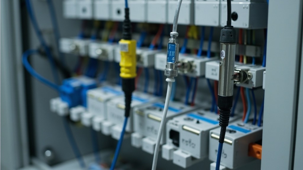
Choosing between a thermocouple and an RTD for your temperature measurement application involves balancing several factors including the sensor’s operating range, accuracy, cost, and compatibility with your existing control system. This article will guide you through the key differences between thermocouples and RTDs, explain the critical calculations for each, and provide a structured approach to selecting, installing, and troubleshooting these sensors. By the end, you will be able to specify the right sensor type and wiring configuration for your temperature measurement needs.
Why the Wrong Sensor Fails Quietly
Selecting the wrong temperature sensor can lead to inaccurate readings, system downtime, and costly repairs. Thermocouples and RTDs operate on fundamentally different principles. A thermocouple generates a voltage proportional to the temperature difference between its hot and cold junctions, while an RTD changes resistance with temperature, typically using a platinum element.
Thermocouple Failure Modes
Thermocouples are susceptible to several failure modes:
- Degradation of the Junction: Over time, the junction of dissimilar metals can corrode or become contaminated, leading to inaccurate readings.
- Poor Cold Junction Compensation: If the reference junction is not at a stable temperature or is improperly compensated, the measurement will drift.
- Incorrect Extension Wire: Using the wrong type of extension wire or mixing wire types can create unwanted junctions, causing errors.
RTD Failure Modes
RTDs, while generally more stable, have their own failure modes:
- Lead Resistance Errors: In a two-wire configuration, the resistance of the leads adds to the measured resistance, introducing errors.
- Self-Heating: The excitation current can heat the sensor, causing the temperature to read higher than actual.
- Mechanical Stress: Physical stress on the platinum element can alter its resistance, leading to inaccurate measurements.
Cost Implications
The cost of a thermocouple is generally lower than that of an RTD, but the cost of wiring and installation can be higher due to the need for specific extension wire types and compensation techniques. RTDs, while more expensive upfront, may offer better long-term stability and accuracy, potentially reducing maintenance and recalibration costs.
What Each Sensor Actually Produces
Both sensors answer the same question with different physics, and the arithmetic of each one decides how the signal has to be handled at the input.
Thermocouple Output
A thermocouple generates a voltage at the junction of two dissimilar alloys, proportional to the difference between the measuring junction and the reference junction:
V = S * delta-T
where S is the Seebeck coefficient and delta-T is the difference between the two junction temperatures. For type K the coefficient is about 41 microvolts per degree Celsius near room temperature, and it is not constant across the range, which is why conversion uses the published reference tables rather than a single slope. With the reference junction at 0 degrees Celsius, the type K table gives 20.644 mV at 500 degrees Celsius and about 8.1 mV at 200 degrees Celsius.
Because the signal is a voltage generated at junctions, the reading depends on every metal-to-metal transition in the circuit. It does not depend on the length or the resistance of the wire, which is what makes thermocouples attractive over long runs.
RTD Output
A platinum resistance detector changes resistance with temperature. Above 0 degrees Celsius the relationship follows the Callendar-Van Dusen equation, which reduces to:
R(t) = R0 (1 + At + B*t²)
- R0 = resistance at 0 degrees Celsius, 100 ohm for a Pt100
- A = 3.9083e-3 per degree Celsius
- B = -5.775e-7 per degree Celsius squared
At 100 degrees Celsius:
R = 100 (1 + 0.39083 – 0.005775) = 100 1.385055 = 138.5 ohm
At 200 degrees Celsius:
R = 100 (1 + 0.78166 – 0.023100) = 100 1.758560 = 175.9 ohm
Look at the curvature rather than the totals: the first hundred degrees gives 38.5 ohm of change, the second gives 37.4 ohm. The average gradient of 0.385 ohm per degree Celsius, derived from the alpha coefficient of 0.003851 ohm per ohm per degree Celsius, is close enough for a span estimate over a few tens of degrees and wrong enough to matter across a wide one. Use the table or the polynomial for anything beyond a narrow band.
The Same Temperature, Two Different Instruments
At 200 degrees Celsius the thermocouple presents about 8.1 mV while the Pt100 presents 175.9 ohm. A thermocouple input is a low-level, high-gain voltage measurement that must also know the temperature of its own terminal; an RTD input is a resistance measurement that must push a known current through the element and reject the voltage drop in the leads. The input card is inside the accuracy chain either way, and connecting the right sensor to the wrong input type is one of the more common commissioning faults – it produces a reading that looks plausible and is wrong by an amount that varies with temperature.
Comparison on the Criteria That Decide It
| Criterion | Thermocouple, type K | RTD, Pt100 |
|---|---|---|
| Practical range | Roughly -200 to 1200 degrees Celsius in continuous service, with the real limit set by wire diameter and atmosphere | Roughly -200 to 850 degrees Celsius, element and sheath dependent |
| Tolerance | Class 1 to IEC 60584-2 is typically plus or minus 1.5 degrees Celsius or 0.4 percent of reading, whichever is greater; tighter classes apply over part of the range | Class A to IEC 60751 is plus or minus (0.15 + 0.002 times t) degrees Celsius, Class B plus or minus (0.30 + 0.005 times t) |
| Stability over time | Moderate; alloy drift and junction degradation shift calibration between checks | Good; platinum is the more stable of the two |
| Signal conditioning | Millivolt signal needs a low-noise, cold-junction-corrected input | Resistance change is large and straightforward to digitise |
| Response time | Set by junction construction and sheath mass, not by the effect itself | Set by sheath mass and the element’s own time constant |
| Wiring | Correct alloy type and polarity; every junction must be compensated | Lead resistance is in series with the element; use three-wire or four-wire |
| Cost | Low sensor cost, more expensive input channel | Higher sensor cost, simpler input channel |
Where Each Advantage Actually Costs You
- Range is the thermocouple’s genuine advantage. Nothing else in this table is free: a type K reading 1000 degrees
Celsius produces tens of millivolts that must be resolved against a reference junction that is itself wandering by several degrees.
- Accuracy and stability are the RTD’s, and the tolerance formulas above show why. On a Class B element at 200 degrees
Celsius the sensor alone accounts for plus or minus 1.3 degrees; a Class A element at the same temperature accounts for plus or minus 0.55 degrees. Choosing the class is cheaper than choosing a thermocouple and then calibrating around its drift.
- Wire cost goes the other way. Thermocouple extension wire is priced against the alloy, so a long run costs real
money, while RTD cable is ordinary copper – but a long RTD run then needs three-wire or four-wire termination, and every field splice on a three-wire probe breaks the equal-lead-resistance assumption the measurement relies on.
- Interchangeability favours the RTD. Two Class B Pt100 elements of the same range are genuinely interchangeable
within the standard’s tolerance; thermocouple wire from two suppliers can differ enough that replacing a length shifts the calibration.
Fitting the Sensor and Commissioning the Channel
Fitting Steps
- Select the Right Sensor: Choose between a thermocouple and an RTD based on the application requirements.
- Prepare the Wiring: Use the correct type of extension wire for thermocouples and ensure RTDs are wired with the appropriate number of leads (2, 3, or 4).
- Install the Sensor: Mount the sensor in the correct location, ensuring adequate immersion depth and sheath diameter for the desired response time.
- Connect to the Controller: Connect the sensor to the PLC or controller, ensuring proper polarity and cold junction compensation for thermocouples.
- Check Insulation Resistance: Measure the insulation resistance between the element and the sheath to ensure there is no leakage.
- Calibrate the System: Calibrate the temperature measurement system to ensure accurate readings.
Wiring Considerations
- Thermocouple Wiring: Use extension wire of the same type as the thermocouple to maintain accuracy. Ensure the reference junction is at a stable temperature and properly compensated.
- RTD Wiring: For long cable runs, use a three-wire or four-wire configuration to minimize the effect of lead resistance. The choice depends on the required accuracy and cable length.
Three Signatures at the Input
What the Operator Reports
- Reading Pinned at Ambient or Pegged Off-Scale: an open sensor, a pulled terminal or a broken lead.
- Reading Moves When the Cable Is Moved: a loose conductor, a chafed insulation making intermittent contact, or a shield that is grounded at both ends.
- Reading Biased Only at One End of the Range: a reference-junction problem on a thermocouple, or lead resistance on a two-wire RTD.
Ordered Checks
- Check Connections: Ensure all connections are secure and free from corrosion.
- Verify Sensor Type: Confirm that the correct sensor type is used and that the wiring is appropriate.
- Inspect for Damage: Look for any physical damage to the sensor or wiring.
- Test Insulation Resistance: Measure the insulation resistance to check for leakage.
- Recalibrate: Recalibrate the system to ensure accurate readings.
Where Compensation Happens and What the Wire Really Does
The Reference Junction Is Part of the Measurement
A thermocouple measures the difference between two junctions, so the second junction is inside the result. Compensation is not a property of the sensor: it happens at the point where the thermocouple alloys first meet copper, which is the input terminal of the transmitter or the terminal block on the card. A temperature sensor at that point measures the copper-to-alloy junction temperature, and the instrument adds it back into the reading.
Two consequences are worth designing around. If the compensating sensor reads the air an inch away rather than the terminal itself, a warm terminal biases the whole measurement by the difference. And if a controller input configured for thermocouple with internal compensation is fed from a field junction box that is already being compensated, the same correction is applied twice and the reading runs high by roughly the box temperature.
Extension Wire Is Not a Fix for Anything
- Extension wire is made from alloys matched to the thermocouple type, chosen to behave like the thermocouple at a
lower cost where the parent metals allow it. It therefore moves the reference junction from the sensor to the far end of the run, which is what you want when the far end is a stable, compensated terminal.
- It corrects nothing. It does not compensate resistance, and it does not compensate error. The type must match the
sensor and the polarity must be maintained end to end, because every alloy-to-copper transition you introduce is another junction that has to be accounted for.
- Compensation cable, often plain copper, is only correct for the short isothermal distance between a connector and a
controlled terminal.
- Reversed polarity on part of a run, or a mixed type, produces an error that tracks the temperature at the mistake
rather than the process temperature. That signature is how you find a splice that has been there for years.
Self-Heating and Lead Resistance on the RTD Side
An RTD is measured by passing current through it, and that current heats it:
P = I² * R
Industrial excitation is deliberately small, commonly of the order of one milliampere, so a Pt100 dissipates around a tenth of a milliwatt. Multiply that by the dissipation factor in the sensor datasheet, quoted in degrees Celsius per milliwatt, to get the error. The factor depends on how well the heat escapes: the same probe can be several times worse in still air than in a flowing liquid, which is why an RTD can look out of calibration on a dead leg of pipework and correct inside the main stream.
Lead resistance is added directly in series with the element, so a two-wire Pt100 reads high by twice the resistance of the cable. A three-wire arrangement measures one lead and subtracts it, assuming all three leads have equal resistance – true for a factory-terminated probe, often not true after a field repair. A four-wire or Kelvin connection separates the current path from the voltage path and removes the leads from the result entirely. Over a long run on a Pt100, the difference between a two-wire and a properly terminated three-wire measurement can exceed the tolerance of the element itself, which makes the wiring choice part of the accuracy specification rather than part of the installation.
Response Time, Immersion Depth and the Sheath That Decides It
Response time is a thermal mass problem, not an electronics problem, and it is decided by the sheath and the immersion rather than by whether the element is a thermocouple or an RTD.
What Sets the Time Constant
Heat has to reach the sensing element through the tip, the fill material and the sheath wall before the reading moves, so the governing variables are the mass being heated, the wall thickness, and the heat-transfer coefficient of the medium on the outside. An exposed or grounded junction responds in a fraction of a second; the same element inside a 6 mm stainless sheath with ceramic fill is commonly several seconds. Compare only figures published on the same basis, usually T0.63 or T0.9, and only at the flow velocity stated with them – a time constant quoted in moving water means nothing in still air.
Immersion Depth
Heat also travels back out along the sheath, so a probe that is too short is pulled toward the temperature of the boss or the wall it passes through. The usual rule of thumb is to immerse at least ten times the sheath diameter, so a 6 mm probe wants about 60 mm of penetration; in small-bore pipework, insert the probe axially or use a thermowell that reaches the centre stream. Under-immersed sensors read low on a hot line in a cold plant, and the error shrinks as flow rises, which is why the same installation can be acceptable at full load and wrong at turndown.
Sheath Material and Construction
- Austenitic stainless steel is the default: strong, corrosion resistant, and thermally poor compared with copper, so
wall thickness, tip design and the external boundary condition do far more work than the alloy choice.
- High-temperature and aggressive service moves to nickel alloys for sulfidation and carburisation resistance, and to
ceramic protectors in furnaces. Ceramics resist shock and chemistry but conduct heat badly and are brittle, so they slow the response and must be handled and supported accordingly.
- Copper and aluminium sheaths conduct fastest and are the right answer only in benign, non-corrosive media.
- Thin-walled, small-diameter, uninsulated or low-mass constructions respond fastest; heavy thermowells with an air
gap between probe and wall are the common way to turn a fast sensor into a slow measurement.
The choice is a three-way compromise between response, mechanical and chemical protection, and the pressure and flow rating of the assembly. Fix the process requirement first – what accuracy, within what time, in what medium – and then read the sensor’s datasheet against it rather than picking the cheaper element.
Ordered Fault Finding on a Temperature Reading That Will Not Behave
When a temperature reading is not behaving as expected, a systematic approach to fault finding is essential to identify and resolve the issue efficiently. The first step is to verify the sensor’s basic operation by checking the sensor type and its corresponding measurement range. For thermocouples, ensure that the correct type (e.g., K, J, T) is being used and that the polarity is correct. For RTDs, confirm that the resistance-temperature relationship is consistent with the sensor’s specifications, typically using a platinum 100-ohm sensor (Pt100) as a reference.
Step-by-Step Verification
- Check the Sensor Connection: Inspect the wiring connections for any signs of corrosion, loose connections, or damage. For thermocouples, ensure that the extension wire is of the same type as the thermocouple and that the connections are made using the correct polarity. For RTDs, verify that the lead wires are properly connected and that there is no discontinuity in the circuit.
- Measure the Sensor Output: Use a multimeter to measure the voltage output of a thermocouple or the resistance of an RTD. For thermocouples, the voltage should correspond to the temperature difference between the hot and cold junctions. For RTDs, the resistance should match the expected value based on the temperature being measured, typically using a reference table or formula (e.g., for Pt100, R = R0(1 + αT), where R0 is 100 ohms and α is 0.00385/°C).
- Verify the Cold Junction Compensation: For thermocouples, ensure that the cold junction compensation is functioning correctly. This can be done by measuring the ambient temperature at the point where the thermocouple wires connect to the measurement device and comparing it to the compensation value used by the system.
- Check for Interference: Electrical interference can affect the accuracy of temperature readings. Ensure that the wiring is shielded and grounded properly to minimize noise. For RTDs, check for any nearby sources of electromagnetic interference that could affect the resistance measurements.
- Inspect the Sheath and Probe: Examine the sensor’s sheath and probe for any signs of damage or contamination that could affect heat transfer or electrical conductivity. A damaged sheath can lead to inaccurate readings and reduced response time.
Calibration and Replacement
If the fault finding process does not reveal any issues, consider calibrating the sensor to ensure its accuracy. Calibration involves comparing the sensor’s output to a known standard and making any necessary adjustments. If the sensor is found to be out of calibration or damaged, replacement may be the most effective solution. Regular calibration and maintenance are essential to ensure the reliability and accuracy of temperature sensors in industrial applications.
Quick Selection Checklist
- Temperature Range: Verify the sensor can operate within the desired temperature range.
- Accuracy Requirement: Determine the necessary accuracy and choose a sensor that meets these criteria.
- Response Time: Consider the required response time and choose a sensor with an appropriate sheath diameter and immersion depth.
- Cost Constraints: Balance the upfront cost with long-term stability and maintenance requirements.
- Wiring Complexity: Assess the complexity of the wiring and choose a configuration that minimizes errors.
- Environmental Conditions: Consider the operating environment and choose a sensor that can withstand the conditions.
- Compatibility with Controller: Ensure the sensor is compatible with the existing PLC or controller.
- Maintenance Frequency: Evaluate the maintenance requirements and choose a sensor that fits the maintenance schedule.
- Installation Space: Consider the available space for installation and choose a sensor that fits.
- Long-term Stability: Assess the long-term stability requirements and choose a sensor that offers the necessary stability.
FAQ
How do I know if I need a thermocouple or an RTD?
The choice depends on your application. Thermocouples are suitable for high-temperature applications and offer a wide measuring range, while RTDs provide higher accuracy and stability for precision applications.
What is cold junction compensation and why is it important?
Cold junction compensation is necessary because thermocouples measure the temperature difference between the hot and cold junctions. The cold junction must be at a known temperature, and compensation adjusts the reading to account for any changes.
How do I minimize lead resistance errors in RTDs?
Use a three-wire or four-wire configuration to minimize the effect of lead resistance. A four-wire configuration provides the most accurate measurement by eliminating the effect of lead resistance.
What are the common failure modes for thermocouples and RTDs?
Thermocouples can suffer from degradation of the junction, poor cold junction compensation, and incorrect extension wire. RTDs are more susceptible to lead resistance errors, self-heating, and mechanical stress.
Sourcing the Sensor and the Wiring
Xiamen Lisen Trading Co., Ltd supplies thermocouples, RTD probes, transmitter heads, analog input modules and terminal hardware. Tell us the medium, the temperature range, the insert depth and the card you are wiring into, and we will confirm the sensor type, tolerance class and connection before quoting.
Related Temperature Sensors and Inputs
- JUMO 902030/10-402-1001 Temperature Sensor RTD Probe
- IST Pt1000-K1 Temperature Sensor, Industrial RTD Probe
- YOKOGAWA AAI143-H53 Analog Input Module Industrial Use