
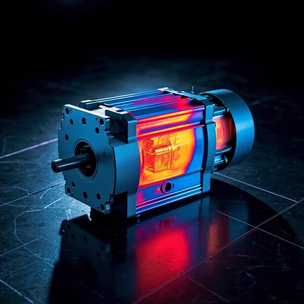
Servo motors are the workhorses of modern automation systems, providing precise control and high performance in applications ranging from robotics and CNC machinery to packaging equipment and aerospace systems. However, one of the most critical factors affecting servo motor performance, longevity, and reliability is temperature rise during operation. Understanding the mechanisms of heat generation, thermal dynamics, and temperature monitoring is essential for engineers, maintenance technicians, and system designers who aim to maximize motor efficiency while preventing catastrophic failures. This comprehensive analysis explores the science behind servo motor temperature rise, measurement techniques, thermal management strategies, and best practices for maintaining optimal operating conditions in industrial environments.
Understanding Servo Motor Temperature Rise
Temperature rise in servo motors refers to the difference between the motor’s operating temperature and the ambient temperature surrounding it. This phenomenon occurs due to inherent inefficiencies in the conversion of electrical energy to mechanical energy. When electrical current flows through the motor windings, a portion of the input power is dissipated as heat rather than being transformed into useful rotational force. This process, known as copper loss or I²R loss, represents one of the primary sources of thermal energy generation within servo motors.
Fundamental Heat Generation Sources
The thermal behavior of servo motors is influenced by multiple interconnected factors that collectively determine the final operating temperature. These heat sources can be categorized into several distinct types, each playing a significant role in the overall thermal balance of the system.
- Copper Losses (I²R Losses): Electrical resistance in the stator and rotor windings converts electrical energy into heat according to the formula P = I²R, where current squared is multiplied by resistance.
- Iron Losses (Core Losses): Hysteresis and eddy current losses in the motor’s iron core contribute significantly to heat generation, particularly during high-frequency operation.
- Friction Losses: Bearing friction, brush friction (in brushed motors), and windage losses create additional thermal energy.
- Stray Load Losses: Imperfections in magnetic circuits and harmonics generate secondary losses that manifest as heat.
- Mechanical Load Effects: Driven loads that create excessive torque or mechanical stress can increase motor temperatures substantially.
Thermal Resistance and Heat Transfer Mechanisms
The temperature rise of a servo motor is governed by the fundamental relationship between heat generation rate and the motor’s ability to dissipate this heat to the surrounding environment. Thermal resistance is a critical parameter that quantifies how effectively a motor can transfer heat from its internal components to the external environment. Understanding thermal resistance pathways is essential for accurate temperature prediction and thermal management design.
Heat Transfer Pathways
| Heat Transfer Mode | Description | Significance in Servo Motors |
|---|---|---|
| Conduction | Heat transfer through solid materials from hot to cold regions | Primary mechanism for heat flow from windings to motor housing |
| Convection | Heat transfer via fluid motion (air or liquid coolant) | Critical for heat dissipation from motor surface to environment |
| Radiation | Electromagnetic heat emission from surfaces | Minor contribution at typical operating temperatures below 150°C |
Effects of Excessive Temperature Rise
When servo motors operate beyond their designed temperature limits, numerous detrimental effects can occur that compromise performance, reduce lifespan, and potentially cause immediate failure. Understanding these consequences is vital for implementing appropriate preventive measures.
Insulation Degradation
The insulation materials used in motor windings are particularly susceptible to thermal degradation. Every 10°C increase in operating temperature approximately halves the insulation’s expected lifespan according to the Arrhenius equation for thermal aging. This exponential relationship means that modest temperature overruns can dramatically accelerate insulation breakdown, leading to shorts, ground faults, and complete motor failure.
Permanent Magnet Demagnetization
Many servo motors utilize rare-earth permanent magnets such as neodymium-iron-boron (NdFeB) in their rotor construction. These magnets experience progressive demagnetization when exposed to temperatures approaching or exceeding their curie temperature. Even temperatures below the curie point can cause reversible demagnetization effects, resulting in reduced torque output, degraded position accuracy, and compromised speed regulation.
⚠️ Important Warning:
Operating servo motors continuously above their thermal limits can void manufacturer warranties and create significant safety hazards. Thermal runaway conditions, where increasing temperature causes further degradation and greater heat generation, can lead to motor seizure, fire, or explosion in extreme cases. Always implement proper thermal protection and monitoring systems.
Mechanical Component Stress
Elevated temperatures affect mechanical components including bearings, seals, and housing materials. Thermal expansion can alter clearances in bearing fits, leading to increased friction and wear. Seal materials may harden or become brittle, compromising environmental protection. Housing materials can deform, affecting shaft alignment and increasing vibration levels.
Temperature Rise Standards and Specifications
International standards define acceptable temperature limits and measurement methods for electric motors, providing engineers with consistent guidelines for design and evaluation. These standards establish thermal class ratings that specify maximum allowable temperatures for insulation systems.
| Insulation Class | Maximum Temperature (°C) | Typical Materials | Common Applications |
|---|---|---|---|
| Class B | 130 | Polyester, polyimide films | General purpose industrial |
| Class F | 155 | Fluoropolymers, epoxy resins | High-performance servo systems |
| Class H | 180 | Silicone, polyimide (Kapton) | Severe duty, aerospace |
| Class N | 200 | Polyimide composites | High-temperature environments |
Measurement Techniques for Temperature Rise
Accurate temperature measurement is essential for validating thermal designs, verifying compliance with specifications, and implementing effective thermal management strategies. Several established methods exist for determining servo motor temperature rise during operation.
Resistance Method (Change of Resistance)
This widely-used technique exploits the linear relationship between conductor resistance and temperature. By measuring winding resistance before and during operation, engineers can calculate the average winding temperature using the temperature coefficient of copper. The formula T = [(R_hot/R_cold) – 1] × (234.5) + T_cold provides accurate results when ambient temperature is known. This method is particularly valuable for continuous monitoring applications and requires precise resistance measurement equipment.
Embedded Temperature Sensors
Modern servo motors frequently incorporate temperature-sensing elements embedded within the windings or mounted on critical components. These sensors provide real-time temperature data for protection and control systems.
- Thermistors (NTC/PTC): Temperature-dependent resistors offering high sensitivity in specific ranges, ideal for protection circuits.
- Thermocouples: Dissimilar metal junctions providing wide temperature range measurement and rapid response times.
- RTDs (Resistance Temperature Detectors): Precision sensors typically using platinum elements for accurate, linear temperature measurement.
- Infrared Thermography: Non-contact temperature mapping using thermal cameras to identify hot spots and thermal gradients.
- Thermal Imaging Cameras: Advanced diagnostic tools for comprehensive thermal analysis during operation.
Thermal Analysis and Simulation Methods
Modern engineering practice increasingly relies on computational methods for thermal analysis, enabling designers to predict temperature distribution before physical prototypes are constructed. Finite Element Analysis (FEA) and computational fluid dynamics (CFD) simulations provide detailed insights into thermal behavior under various operating conditions.
Thermal Network Modeling
The lumped parameter thermal model represents the motor as a network of thermal resistances and capacitances, analogous to electrical circuits. This approach allows engineers to calculate transient thermal responses and steady-state temperatures using established network analysis techniques. Thermal resistance values from manufacturer datasheets or empirical testing enable rapid temperature predictions for various loading scenarios.
Browse topics
Categories
Latest insights
Recent posts
- Mastering Multi-Task Program Management: Strategies for Success in 20262026年8月31日
- Coordinate System Switching: A Complete Guide to Seamless Map Projections Transformation2026年8月29日
- Understanding Program Loop Execution: A Complete Guide to Efficient Iteration in Code2026年8月27日
- How to Calculate MTTR (Mean Time to Repair): Formula, Examples & Best Practices2026年8月25日
- MTBF Calculation: A Complete Guide to Mean Time Between Failures2026年8月23日
Browse topics
Categories
Latest insights
Recent posts
- Mastering Multi-Task Program Management: Strategies for Success in 20262026年8月31日
- Coordinate System Switching: A Complete Guide to Seamless Map Projections Transformation2026年8月29日
- Understanding Program Loop Execution: A Complete Guide to Efficient Iteration in Code2026年8月27日
- How to Calculate MTTR (Mean Time to Repair): Formula, Examples & Best Practices2026年8月25日
- MTBF Calculation: A Complete Guide to Mean Time Between Failures2026年8月23日
Discover more from Xiamen Lisen Trading Co., Ltd
Subscribe now to keep reading and get access to the full archive.