
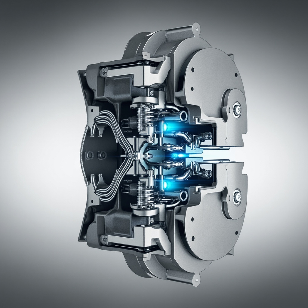
Servo brake configuration is a critical aspect of modern motion control systems, directly impacting the precision, safety, and efficiency of automated machinery. Whether you’re working with CNC machines, robotics, or industrial automation equipment, properly configuring your servo brake system ensures reliable stopping torque, accurate positioning, and extended component lifespan. This comprehensive guide explores the fundamentals, key parameters, and best practices for optimizing your servo brake setup.
Understanding Servo Brake Fundamentals
A servo brake is an electromagnetic or spring-actuated holding device integrated with or attached to a servo motor. Its primary function is to lock the motor shaft when power is removed, preventing unintended movement that could compromise safety or product quality. Servo brakes are essential in vertical axis applications, gravitational load handling, and emergency stop scenarios where uncontrolled motion poses significant risks.
Modern servo brake systems operate on the principle of fail-safe engagement. When electrical current is applied, the brake releases, allowing the motor to rotate freely. When power is interrupted, springs force the friction plates together, creating immediate holding torque. This design philosophy ensures that loss of power results in a safe, controlled stop rather than freewheeling motion.
Key Components of a Servo Brake System
- Brake Coil: Electromagnetic component that, when energized, releases the brake mechanism by overcoming spring tension.
- Friction Plates: High-friction surfaces that create holding torque when compressed against the rotor plate.
- Springs: Provide the mechanical force necessary to engage the brake during power-off conditions.
- Brake Driver Circuit: Electronic control module that manages voltage and current supplied to the brake coil.
- Position Sensors: Monitor brake engagement status and provide feedback to the control system.
- Thermal Management System: Dissipates heat generated during repeated engagement cycles.
Common Servo Brake Configurations
Servo brake configurations vary based on application requirements, load characteristics, and safety standards. The three most prevalent configurations include normally-closed (power-off engaged), normally-open (power-on engaged), and dual-circuit systems for redundant safety applications.
| Configuration Type | Engagement State | Typical Application | Response Time |
|---|---|---|---|
| Normally-Closed (NC) | Engaged when de-energized | Vertical axes, hoisting, safety stops | 10-30 ms |
| Normally-Open (NO) | Engaged when energized | High-speed spindles, dynamic braking | 5-15 ms |
| Dual-Circuit Redundant | Independent dual engagement | Medical robotics, aerospace, elevators | 8-20 ms |
| Spring-Applied Hydraulic Release | Spring engaged, hydraulic release | Heavy machinery, press brakes | 20-50 ms |
Step-by-Step Servo Brake Configuration Process
- Verify Electrical Specifications: Confirm voltage rating (typically 24V DC), current draw, and polarity match your drive system before connection.
- Set Brake Release Delay: Configure the time delay between motor energization and brake release (typically 50-200ms) to prevent torque fighting.
- Configure Brake Engagement Timing: Program the brake to engage only after the motor has stabilized at zero speed, reducing wear and mechanical shock.
- Adjust Holding Torque Parameters: Set torque limits based on load requirements, typically 1.2-1.5 times the maximum static load.
- Test Emergency Stop Function: Validate that the brake engages within specified response time during E-stop activation.
- Calibrate Feedback Signals: Verify brake status output signals are accurate and integrated properly with the control system.
- Document Configuration Settings: Record all parameters, including voltage, timing, and torque values, for future reference and maintenance.
Critical Configuration Parameters
| Parameter | Recommended Range | Impact on Performance |
|---|---|---|
| Operating Voltage | 24V DC ±10% | Affects release time and coil temperature |
| Release Time | 30-150 ms | Determines start-up smoothness |
| Engagement Time | 10-50 ms | Critical for safety and stopping accuracy |
| Holding Torque | 1.0-3.0 Nm (small motors) | Must exceed maximum static load torque |
| Backlash | Less than 1° | Affects positioning accuracy |
⚠️ Critical Safety Warning: Never bypass or disable a servo brake in vertical axis applications or where gravitational loads are present. Always test emergency stop functionality after any configuration change. Improperly configured brakes can result in equipment damage, product loss, or serious personal injury. Ensure all configuration work is performed by qualified personnel following local safety regulations and manufacturer guidelines.
Troubleshooting Common Configuration Issues
Even with careful configuration, servo brake systems can experience issues that affect performance. The most frequent problems include delayed release, insufficient holding torque, excessive heat generation, and premature wear. Each of these issues typically stems from specific configuration errors that can be identified and corrected systematically.
- Brake Won’t Release: Check voltage supply, wiring polarity, and ensure drive enable signal is active before brake release command.
- Slow Release Time: Verify coil resistance, check for voltage drop across connections, and inspect for contaminated friction surfaces.
- Slippage Under Load: Increase holding torque specification, inspect friction plate wear, and verify proper installation torque on mounting bolts.
- Excessive Noise During Engagement: Adjust engagement timing, check for misalignment, and verify damping components are functioning correctly.
- Overheating: Reduce cycle frequency, improve ventilation, and verify that voltage does not exceed rated specifications.
Industry Applications and Best Practices
Servo brake configuration requirements vary significantly across industries. In semiconductor manufacturing, ultra-precise positioning demands minimal backlash and rapid response. Material handling systems require robust holding capacity for variable loads. Medical robotics applications prioritize redundancy and fail-safe operation, often requiring dual-circuit configurations with continuous monitoring.
Best practices for optimal servo brake configuration include establishing a regular maintenance schedule, keeping detailed configuration records, conducting periodic safety audits, and training operators on proper system behavior. Implementing condition monitoring through vibration analysis and temperature sensors can provide early warning of developing issues, allowing for planned maintenance rather than unexpected downtime.
When selecting and configuring a servo brake, always consider the total system inertia, maximum deceleration requirements, duty cycle, ambient conditions, and applicable safety standards such as ISO 13849 or IEC 61508. Working with reputable manufacturers and following their detailed configuration guides ensures compatibility and reliability throughout the system’s operational life.