
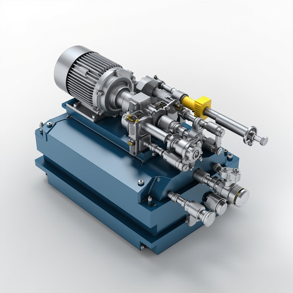
A hydraulic station, also known as a hydraulic power unit (HPU), is the heart of any hydraulic system, providing the pressurized fluid necessary to drive actuators, motors, and cylinders. Effective hydraulic station design is critical to ensuring system reliability, energy efficiency, operational safety, and long service life. Whether you are designing a unit for industrial machinery, mobile equipment, marine applications, or aerospace systems, a well-engineered hydraulic station reduces downtime, minimizes heat generation, and optimizes overall performance. This comprehensive guide explores the essential principles, components, calculations, and best practices involved in modern hydraulic station design.
Core Components of a Hydraulic Station
A standard hydraulic power unit integrates several interconnected subsystems. Understanding each component is fundamental to creating a balanced and efficient design.
- Prime Mover (Electric Motor or Diesel Engine): Provides the mechanical input power, typically sized based on flow and pressure requirements.
- Hydraulic Pump: Converts mechanical energy into hydraulic energy; common types include gear, vane, and piston pumps.
- Reservoir (Tank): Stores hydraulic fluid, dissipates heat, separates air and contaminants, and accommodates volume changes.
- Filtration System: Removes particulate contamination to protect components and extend fluid life.
- Valve Manifold: Controls flow direction, pressure, and flow rate through directional, pressure, and flow control valves.
- Cooling and Heating Elements: Maintain optimal fluid temperature using heat exchangers, coolers, or immersion heaters.
- Pressure Gauges and Sensors: Monitor system parameters for diagnostics and control feedback.
- Accumulator: Stores pressurized fluid to supplement pump flow, absorb shocks, and maintain pressure during peak demands.
Step-by-Step Hydraulic Station Design Process
1. Define System Requirements
Begin by determining the maximum operating pressure, required flow rate, duty cycle, ambient conditions, fluid type, and applicable industry standards (ISO 4413, NFPA T2.6.1, or DIN 24312). These parameters drive every subsequent design decision.
2. Calculate Pump and Motor Sizing
Use the standard hydraulic power formula:
Hydraulic Power (kW) = (Flow × Pressure) / 600
Motor Power (kW) = Hydraulic Power / Pump Efficiency × 1.1 (safety factor)
For example, a system requiring 50 L/min at 210 bar with 90% pump efficiency needs approximately 19.4 kW of input power.
3. Reservoir Sizing
| System Type | Reservoir Volume Rule | Typical Capacity |
|---|---|---|
| Industrial Stationary | 2 to 4 × pump flow per minute | 100–500 L |
| Mobile Equipment | 1 to 1.5 × pump flow per minute | 30–150 L |
| High-Pressure Systems | 3 to 5 × pump flow per minute | 200–1000 L |
4. Heat Dissipation and Cooling Design
Approximately 20–30% of input power is converted into heat due to inefficiencies. Heat generation is calculated as:
Heat Generated (W) = (1 − Pump Efficiency) × Input Power × 1000
If natural reservoir cooling is insufficient, air-oil or water-oil heat exchangers must be specified. Maintain fluid temperature between 30°C and 60°C for optimal viscosity and seal performance.
Filtration and Contamination Control
Contamination is the leading cause of hydraulic system failure. Modern design standards (ISO 4406) define cleanliness levels. Recommended filtration ratings for hydraulic stations are:
- Pressure Line Filtration: 10–25 μm absolute, β₁₀ ≥ 75
- Return Line Filtration: 25–40 μm nominal
- Suction Strainer: 100–150 μm to protect pump from large debris
- Off-line Kidney Loop Filtration: 3–10 μm for high-precision systems
Common Hydraulic Station Configurations
| Configuration | Best Application | Efficiency Rating |
|---|---|---|
| Fixed Displacement + Relief Valve | Simple presses, low-duty cycles | Low (60–70%) |
| Variable Displacement Pump | Machine tools, injection molding | High (80–90%) |
| Load-Sensing System | Mobile hydraulics, forestry | Very High (85–95%) |
| Servo-Proportional Station | Aerospace, precision testing | Excellent (90%+) with response control |
Safety and Compliance Considerations
Hydraulic station design must comply with regional and international safety standards. Essential safety features include:
- Pressure Relief Valves: Mandatory on every circuit to prevent over-pressurization.
- Emergency Stop Circuits: Cut power to the motor instantly on demand.
- Leak Detection: Bunded reservoir base and level indicators prevent environmental contamination.
- Noise Reduction: Sound enclosures and flexible couplings to meet OSHA 85 dB(A) limits.
- Temperature Protection: Automatic shutdown if fluid exceeds 80°C.
- Lockout/Tagout (LOTO): Provisions for safe maintenance isolation.
Best Practices for Long-Term Reliability
To maximize the operational life of your hydraulic station, follow these proven design strategies:
- Keep suction lines short, large-diameter, and free of sharp bends to prevent cavitation.
- Position the reservoir above the pump inlet whenever possible to ensure